Engineering
You are logged in as xxxx. Logout
Question
This question has been answered by 32 people and has an average rating of 4.00 (based on 27 ratings)
A frame structure consisting of 3 columns, connected by beams, are supported by a pin support (left), a roller support (middle), and another roller support (middle). The frame is subjected to a downward load, which is placed on the beam, between the middle and right columns.
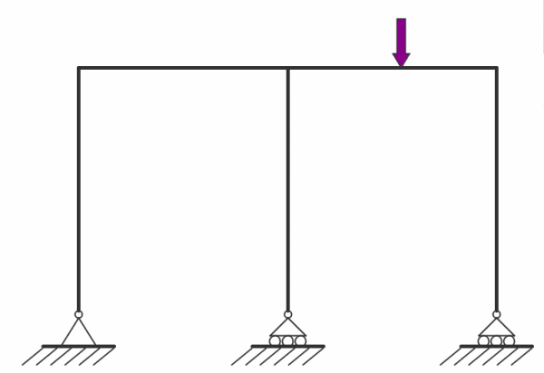
Ignoring self weight, determine the deflected shape the load causes to the structure:
Alternatives
| Option | Alternative | First answers |
Confirmed answers |
|---|---|---|---|
| A |
|
3 (9.38%) |
0 (0.00%) |
| B |
|
5 (15.63%) |
0 (0.00%) |
| C |
|
10 (31.25%) |
3 (100.00%) |
| D |
|
12 (37.50%) |
0 (0.00%) |
| E |
None of the above. |
2 (6.25%) |
0 (0.00%) |
Explanation
The following explanation has been provided relating to this question:
Topics
The following topics have been indicated as being relevant to this question:
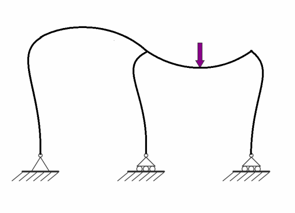
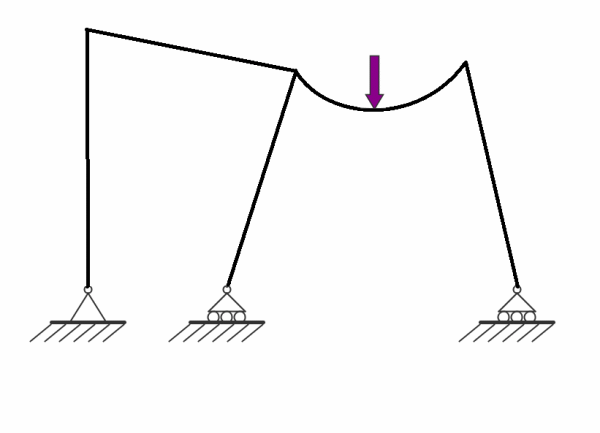
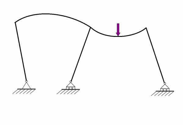
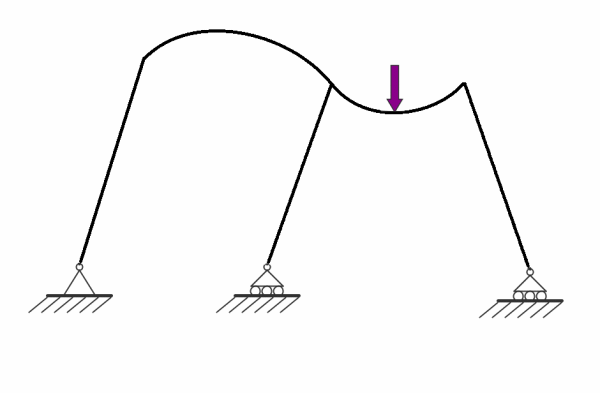

credit: http://expeditionworkshed.org/applets/2D_frames/sketch_17/sketch_17.html
Correct answer is: C
Option A: a pin and roller support does not produce moments, so the columns near the support should not be rigid while the rest of the columns are bent. The roller supports should have slid horizontally (hence roller support), as they cannot produce horizontal forces to counteract the result of the deflection (with the columns being right angled with the beam). They can only produce vertical forces. And a pin support can only produce vertical and horizontal forces, no moments.
credit: by D.L.S.. A masterpiece; drawn with elegance and beauty.
Option B: Incorrect - due to the left beam not being deflected. using the figure I have drawn, we can see that on the second beam produces a "smile" deflection shape due to the load, and the portion of the beam on the left does not deflect and is parallel to the tangent of the deflected portion of the beam at the left support. BUT using a 3 support beam, the left side is now held down by a pin support, so the left portion is now deflected, is a "frown" shape. Translating this to the frame deflection, the left portion should have have a "frown" deflection, but rather, it is not deflected so it is incorrect.
Option C: correct! Again, using the figure I have drawn, we can clearly see that the beam at the top follows the correct deflection. Now, for the orientation of the columns. Using the analogy of the simple 3-support beam example in my drawing, we can see that the deflection on the left portion produces a "frown" shape, meaning that the centre of deflection is at the bottom of the beam, meaning that the left and middle supports should be closer than in the initial set-up (the middle support can move horizontally). While on the right portion, it produces a "smile" shape, meaning that the centre of deflection is above the beam, meaning that the middle and right supports should be farther apart than in the intial set-up (the middle and right support can move horizontally). Hence C is correct
Option D: Incorrect. Almost correct except the positioning of the left support and the orientation of the left column. As I have discussed The support should be closer together (as the rolling support can move horizontally), and that the left and middle column should point towards the centre of deflection. However the left and middle support are of the same distance and the left column is not pointing towards the centre of deflection, so it is incorrect.
Option E: Incorrect. Because Option C is correct, meaning there IS an answer above E, making the statement false, thus incorrect.